
Although the roots of today’s Coriolis flowmeters can be traced back to the 1950s, it was not until 1977 that Micro Motion introduced a commercially viable Coriolis flowmeter for industrial applications. Since that time, a number of other suppliers have entered the market, including Endress+Hauser and KROHNE. The principle underlying the Coriolis flowmeter, however, dates back to 1835, when French mathematician Gaspard Gustave de Coriolis showed that an inertial force needs to be taken into account when describing the motion of bodies in a rotating frame of reference. A hypothetical object thrown from the North Pole to the equator, for example, appears to vary from its intended path due to the earth’s rotation — and this illustrates the Coriolis force.

Coriolis wrote a very influential paper in 1835, “Mémoire: sur les équations du mouvement relatif des systèmes de corps” that eventually became the basis for what is known today as the Coriolis force. Flow Research translated this paper into English. (Download both above.) While some commentators have stated that this article was about waterwheels, Coriolis does not mention waterwheels in his paper. Instead, he limits his discussion to rotating frames of reference. His main point is that in order to account for motion around a rotating frame of reference, it is necessary to introduce what he calls compound centrifugal forces. These compound centrifugal forces are what later became known as Coriolis forces. It is also important to be aware that Coriolis did not discuss meteorology or what is now known as the “Coriolis effect” on weather systems in his article.
More on Coriolis flowmeters:
- So why are they called Coriolis meters?
- How they work
- A different perspective on the Coriolis principle of operation
- Supplier differentiation
- Advantages & disadvantages
- Frontiers of research
So why are they called Coriolis meters?
How did the term ‘Coriolis’ become attached to a certain type of flowmeter — even though we maintain that they do not actually use the Coriolis effect? The following timeline illustrates how the term ‘Coriolis’ became associated with mass flowmeter technology, even as the physical mechanisms shifted significantly:
- In 1958, Roby White patented a device that rotated the fluid flow and relied on the actual Coriolis force arising from angular motion. He explicitly called it a ‘Coriolis Mass Flowmeter.’
- In the 1960s, other designs continued this trend of using mechanical rotation to invoke the Coriolis effect.
- In 1965, Anatole Sipin substituted oscillation for rotation and described achieving “Coriolis-like” forces.
- In 1975, Jim Smith applied for a new patent that build on Sipin’s design. He described using oscillating tubes instead of rotating flow. Despite the lack of true rotation, he retained the term ‘Coriolis,’ likely due to continuity with earlier patents. This patent was granted in 1978.
- By 1977, with the founding of Micro Motion and commercialization of Smith’s design, the term ‘Coriolis flowmeter’ was fully established in industry—even though the underlying physics was better explained by fluid inertia than by true Coriolis forces.
Today, the name persists for historical and mathematical reasons, even though ‘inertial mass meter’ might be a more accurate descriptor.
The patents granted in the 1950s and 1960s that described flowmeters that rotated the flow were not commercialized and were most likely not practical. This was the criticism of Anatole Sipin, who had three different patents approved from 1965 to 1967. He makes the following comments in his 1965 patent:
“Other mass flowmeters that have obstruction-free flow passages are the rotating or oscillating gyroscopic meters of which several types are known. The gyroscopic meter has the disadvantage of requiring at least one and sometimes several loops with associated bends and turns between the flow inlet and outlet. For accurate flow measurement, moreover, the diameter of the loop must be ten to twenty or more times as large as the diameter of the flow passage (assuming circular cross-sections); and this requirement makes the apparatus large and cumbersome for the flow range… In addition, the rotating gyroscopic type of meter requires rotating fluid seals, introducing serious leakage and friction problems.”
In place of earlier designs, by Anatole Sipin in Patent 3,218,851 proposes using an oscillating design. This patent was filed in 1961 and approved in 1965. Sipin proposes the following:
“The mass flow measuring principle used in the embodiments of this invention is that where an oscillatory motion is applied by a member to a bounded stream of material and there is a changing difference between a transverse momentum, that is momentum orthogonal to the axis of flow, or the fluent material entering the oscillating member and that leaving the oscillating member, mechanical energy is removed from the oscillating member and added to the stream at a rate directly proportional to the mass rate of flow.”
In discussing his invention, Sipin does not claim to be employing the Coriolis force, though he says that what he is doing is “equivalent to the Coriolis force” and “equivalent to the Coriolis acceleration.” Furthermore, he called his patent “Mass Flowmeter Systems,” not making an explicit reference in the title to Coriolis flowmeter.
When Jim Smith applied for his patent in 1975, built on Sipin’s idea of oscillation instead of rotation and proposed using the difference in phase shift between the incoming fluid and the outgoing fluid in a bent pipe to measure mass flow.
Jim Smith in his patent, which was approved in 1978, called his invention “Method and Apparatus for Mass Flow Measurement.” He cited three previous patents by Anatole Sipin as supporting documents. However, he drops Sipin’s more cautious phrasing of “equivalent to the Coriolis force” and “equivalent to the Coriolis acceleration.”
In Smith’s abstract, he appeals directly to the Coriolis force, saying that his device measures “the torque generated by the Coriolis force.” At this point, the move from rotation to oscillation was complete, and Coriolis flowmeters were born as devices that oscillate the flow.
Click here for more detail on the patents themselves.
How they work
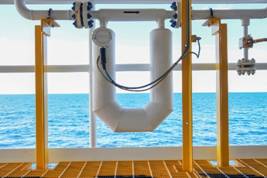
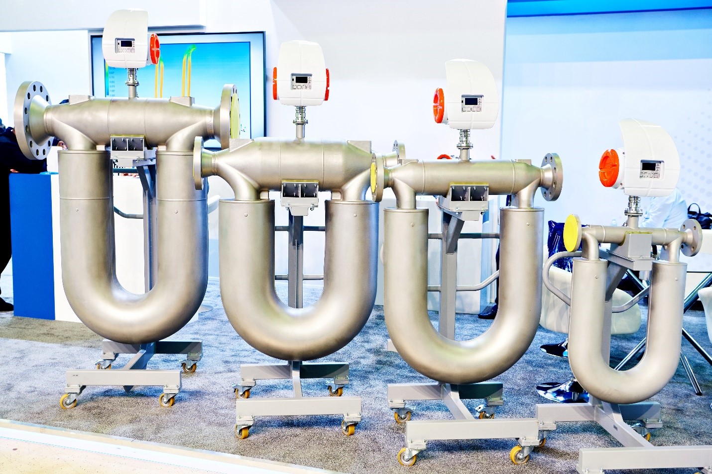
Modern Coriolis flowmeters today typically consist of one or two vibrating tubes with an inlet and an outlet. These tubes can either be straight or bent, though the large majority are bent.
Whether they are single or dual, bent or straight, Coriolis flowmeters rely on oscillating tubes. The tubes are made to oscillate at their natural resonant frequency by an electromagnetic exciter or drive coil located at the apex of the tubes. The apex is the highest point of the tube, and it is where the inlet ends, and the outlet begins. Another way of describing the apex is that it is the central point between the beginning of the tube and the end of the tube.
The peak amplitude of vibration is at the apex of the flow tube or tubes. Magnet and coil assemblies called pickoffs are mounted at the same corresponding place on the inlet and the outlet portions of the flow tube(s). As the tubes oscillate, the voltage generated from each pickoff creates a sine wave. When there is no flow, the inlet and outlet sine waves are in phase. Being in phase means that they are in a synchronized motion.
When fluid is not moving through the tube, the inlet and outlet sine waves are in phase. Being in phase means that they are in a synchronized motion. This means that the waves are moving at
the same rate and exactly together. When two people synchronize their watches, they set them to the same time so that the watches are moving together, and both tell the same time. Under no-flow conditions, the size waves generated by the pickoffs on the inlet and outlet side look exactly the same.
When fluid moves through the tube, the inertial force of the fluid causes the tube to oscillating. This results in a phase shift, or time difference, between the sine waves on the inlet side of the tube and the sine waves on the outlet side of the tube. The sine waves generated by the pickoff coils on the inlet and outlet side of the tube are no longer in phase; instead, they are asynchronous. There is now a difference in time between these sine waves, which is measured in microseconds. This difference in time is called delta T (ΔT), and is directly proportional to mass flowrate. The mass flowrate is computed by the transmitter, which outputs this value along with other desired values such as density, volumetric flow, and temperature.
While the amount of the phase shift or ΔT is directly proportional to mass flowrate, the sine wave frequency indicates density. Frequency means the number of waves per second. A heavy fluid like honey will have a lower frequency than a lighter liquid such as water. Some Coriolis meters are used to measure density rather than flow, but generally both values are desired.
Coriolis flowmeters contain one or more vibrating tubes. These tubes are usually bent, although straight-tube meters are also available. The fluid to be measured passes through the vibrating tubes. It accelerates as it flows toward the maximum vibration point and slows down as it leaves that point. This causes the tubes to twist. The amount of twisting is directly proportional to mass flow. Position sensors detect tube positions.
A different perspective on the Coriolis principle of operation
For many years, I [Jesse Yoder] have questioned why Coriolis flowmeters are called “Coriolis” meters. I even wrote an article for Flow Control in 2011 arguing they should be called “inertial mass meters,” and discussing whether they embody the Coriolis principle.
I’ve discussed this terminology with the top engineers and designers at the leading Coriolis companies in the US, UK, and Switzerland. I have even had discussions with colleagues from Germany who have spent 25 years designing these meters. These are the main points we discussed:
1. It is believed that Coriolis meters employ a force that governs the behavior of bodies in a rotational frame of reference. This is sometimes called a Coriolis force.
2. Coriolis meters do not employ the “Coriolis effect,” which has to do with the observed deflection of a body moving over a rotating platform. This is what Gustave Coriolis was referring to when he wrote about storms being deflected as they move north from the equator.
3. Once you remove the Coriolis effect from the equation, there is no longer any reason to call the meters “Coriolis” meters. Perhaps “oscillating meters” would be more accurate.
This is something I’ve struggled with for over 10 years and now at last, I see a solution!
To clarify, Coriolis meters are the most accurate meter made and they solve a lot of flow problems that other meters don’t. I’m not saying we should change their name. I am saying that Coriolis meters don’t make use of the Coriolis effect.
This has been dubbed a “Coriolis force” by people like Yao Tzu Li who patented an early version of this meter in 1960 and by Anatole Sipin who has three patents in the 1960s. This terminology was picked up by dozens of later patents. The problem is that Gustave Coriolis was talking about a “fictitious” force that was described after his death (1843) as the Coriolis effect. It refers to the apparent effect on the motion of an object passing over a rotating frame of reference when viewed from the perspective pf the point of origin that moving object. The force exerted by the oscillating tubes of a Coriolis meter on the fluid is a real force, but it is due to the fluid movement along a small portion of a circle. It is unrelated to Gustave’s Coriolis effect.
Supplier differentiation
Coriolis suppliers have introduced a wide variety of models and types of Coriolis flowmeters in the past 35+ years and differentiate themselves in a number of ways. One is by the proprietary design of the bent tubes. Another is by the different types of straight tube Coriolis flowmeters they offer.
Suppliers also compete by bringing out Coriolis flowmeters for particular industries and applications, such as food & beverage and pharmaceutical. Accuracy and other performance specifications are other areas of supplier differentiation.
While Coriolis flowmeters are loved by many end users, price is often an issue. Coriolis flowmeters are the most expensive meter made, in terms of average selling price. The average selling price of Coriolis flowmeters are between $5,000 and $6,000. Some suppliers have introduced low-cost Coriolis flowmeters in the $3,000 range.
Performance specifications for the lower-cost flowmeters are not at the same level as those of the higher-priced meters. However, these lower-cost meters can help satisfy the needs of users who want the essential benefits of Coriolis technology but prefer not to pay the higher price.
Coriolis flowmeters are used to measure both liquids and gases, but they do have some limitations with gas flows. Coriolis meters have an easier time measuring liquids than gases because liquids are denser than gases.
Advantages and disadvantages
of Coriolis meters
| ADVANTAGES | DISADVANTAGES |
| High accuracy | High initial cost |
| Approved for custody transfer for liquid and gas applications | Becomes expensive and unwieldy in line sizes above four inches |
| Now available for line sizes above six inches | Gas flow measurement can be difficult due to low density of gas |
| Can handle sanitary applications | Pressure drop for bent-tube meters |
| Excel in line sizes of two inches and less | Can have a problem measuring liquids with entrained gas |
| High reliability, low maintenance | |
| Much new product development ongoing |
Frontiers of research for Coriolis meters

Larger line sizes
Building large and larger line size Coriolis flow meters is a frontier of research for this meter type. The largest line size currently built is a 16-inch meter built by Endress+Hauser. This happens to be a limit also shared by vortex and positive displacement meters. It is not clear why a larger Coriolis meter cannot be built, but such a meter would have to overcome several barriers:
- The meter would presumably have to be even larger and heavier than the current large line-size meters. This would make it even more difficult to move around and install than existing meters. So far no one has been able to build a 20-inch meter.
- As the meter gets larger, it becomes more difficult to vibrate the meter in such a way that it can reliably indicate mass flow. This is due to the increased weight of the meter.
- Any meter that is larger than the existing meters would be even more expensive than the existing line size meters, some of which sell for $75,000. End-users would likely look for an alternative technology such as ultrasonic or turbine if these other meters could satisfy their needs for considerably less cost.
Perhaps these technological barriers to creating a larger Coriolis meter can be overcome. One problem is finding a meter tube that can be effectively vibrated in a way that mass flow can be measured. Due to its size, this may require finding stronger and lighter materials of construction.
Another problem is the weight and size of a 20-inch meter. Finding stronger and lighter materials of construction may also solve this problem.
Several manufacturers have readied the designs of larger meters, but are waiting for the right market application to introduce them. The right market application involves a very expensive fluid with high accuracy requirements and a significant throughput. It is likely that 20-inch Coriolis meters will happen when a manufacturer decides it is a worthwhile investment to make in expanding their product line.
Higher accuracy gas flowmeters
According to Flow Research data, Coriolis meters for gas typically have 0.35% accuracy, while Coriolis meters for liquids can measure accuracies as high as 0.05%. Because gases are lighter and less dense than liquids, it is, at present, impossible for Coriolis meters for gas to achieve the same accuracy levels as those for liquids.
Here the solution again seems to be to find materials of construction that are lighter and more responsive to the less dense gases and yet can be subject to vibration or oscillation. Not until this can be done will Coriolis meters be able to seriously compete with ultrasonic meters for certain custody transfer of natural gas applications. This especially applies to those with 12-inch and up line sizes. This is a serious subject for research and development, but it is not clear what the technological limitations are.
Addressing the vibration problem
Coriolis meter body vibrations can be thrown off by external vibrations from heavy machinery, railroad trains and trucks, or electrical machinery. It is not clear how prevalent a problem this is, but it is a known problem for Coriolis meters. It is also a problem for vortex meters, and vortex suppliers addressed the issue through software. End-users are advised to check for potential vibration issues before installing a Coriolis meter. Apart from taking these possibilities into account in mounting the meter, it is not clear how to address this problem. Some suppliers, however, say they have addressed it. This is a frontier of research for Coriolis meters.
Blogs
Click here to read Jesse Yoder’s blogs about Coriolis.
Coriolis research
Please visit our parent Flow Research site to learn about The World Market for Coriolis Flowmeters, 8th Edition, published in August 2025,